
Watering Houseplants through the Cloud
This summer, I endeavored on a few different IoT projects. Earlier in the summer, I shared my weather station project. I took some of the concepts from that, and built an automated watering system for houseplants that currently reside in our kitchen. Here is a picture of the shelf that holds the plants that are automatically watered:

The little wooden box houses all the components, and there are hidden wires behind the shelfs arms that are connected to the two plants at the top.
This project was a lot of fun, and a great learning experience. As someone still new to IoT, this project gave me a lot of hands on experience with different technologies I wouldn’t have otherwise used. It also was a great experience of development, as I built and rebuilt several parts of this as I learned how they worked and fixed issues I had.
In this project, I learned how to solder wires, worked with my first esp32, learned how to wire relays, all the while, making a fun project for my family (and even made it look nice as I stored all the electronics in a pretty wooden box provided by my wife after a trip to HomeGoods). Here’s a picture of the wooden box with everything connected:

I’ll be discussing the boxes components in the next sections.
My project connected Firebase, Twilio, the world of Raspberry Pi, two esp32s, and some other small electronic components into an automated watering system that is self-contained.
This post is going to walk through my project, and how I connected the technologies mentioned. I’m also going to discuss some recommendations for anyone looking to do something like this.
The Big Picture
So before I go into all the pieces of the project, I’ll start with a high level explanation of how it works.
First off, the project has moisture sensors in the two plants at the top like you see here:

These moisture sensors are connected to esp32s that take in the moisture readings and then do POST calls to a Firebase Firestore database I have setup. The esp32s that I have connected take moisture readings once an hour and send those up to Firebase.
Separately, I have a Raspberry Pi that polls Firebase throughout the day. Once a day, a cron job runs and checks the moisture readings sent up by the esp32s. If the moisture readings are below the “watered” threshold I setup, then the Raspberry Pi connects a relay to water the plants. The relay essentially closes a circuit that powers two pumps that you see in the mason jars next to the plants. Here are the pumps up close:

When the Raspberry Pi completes the circuit, the submersible pumps are powered and deliver water to the plants.
Additional Features
I also connected an API I built with Firebase Functions and Twilio to be able to interact with this system over text.
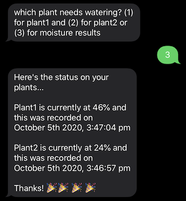
When the plants get watered, I get a text message saying the status and whether or not they are watered. Here’s a screenshot of the daily text message:

I also can text a chatbot I have setup, so that I can water the plants or check on their moisture settings. Here’s a screenshot of me interacting with the chatbot to water the plants:
This all makes it easy to maintain, as I can interact with the chatbot when I want to do anything. Since it is automated, I also only need to periodically fill up the mason jars as the plants get watered.
More about the technology used
So in order to do all of this, I set up an API with Firebase Functions. I have different API endpoints for the different operations that the plants might need.
app.post("/api/water-request", (req, res) => {
  (async () => {
    try {
      await firestore.waterRequest(db, req.body.plant);
      return res.status(200).send();
    } catch (error) {
      console.log(error);
      return res.status(500).send(error);
    }
  })();
});

/**
 * called by Raspberry Pi to get any water requests, and clear them out also
 */
app.get("/api/water-results", (req, res) => {
  (async () => {
    try {
      const message = await firestore.waterResults(db);
      console.log("water results called successfully");
      console.log(JSON.stringify(message));
      return res.status(200).send(message);
    } catch (error) {
      console.log(error);
      return res.status(500).send(error);
    }
  })();
});

/**
 * save moisture for plants
 */
app.post("/api/moisture-save", (req, res) => {
  (async () => {
    try {
      await firestore.moistureSave(db, req.body.plant, req.body.percentage);
      console.log("moisture save was done successfully");
      console.log(req.body.plant);
      return res.status(200).send();
    } catch (error) {
      console.log(error);
      return res.status(500).send(error);
    }
  })();
});

/**
 * called to get the current moisture levels of the two plants
 */
app.get("/api/moisture-results", (req, res) => {
  (async () => {
    try {
      const results = await firestore.moistureResults(db);

      let message =
        "Here's the status on your plants...\n" +
        "\n" +
        `Plant1 is currently at ${results.plant1}% and this was recorded on` +
        "\n" +
        `${results.plant1Recorded}` +
        "\n" +
        "\n" +
        `Plant2 is currently at ${results.plant2}% and this was recorded on` +
        "\n" +
        `${results.plant2Recorded}`;

      message = message + "\n" + "\n" + "Thanks! 🎉🎉 🎉 🎉";

      return res.status(200).send(message);
    } catch (error) {
      console.log(error);
      return res.status(500).send(error);
    }
  })();
});
Here are the routes that are called in the API I built. The actual interaction with Firestore I’ve refactored into its own module.
With regards to the esp32s, I used the Arduino IDE to interact with the devices. With the Arduino IDE, you can write programs that are compiled into C++ and use their APIs for the various features. This is dependent upon the device, as some devices compatible with Arduino might not have wifi antennas etc. The esp32 is great because it has pretty much all you need, and is very compact. It’s also very cheap and you can get one for about $15 or less. Here’s one of the esp32s up close (note that I soldered the GPIO assembly onto the board):

Getting started with esp32s is actually pretty easy. The combination of the Arduino IDE and device connections, make it a small learning curve. I also found several videos on YouTube that help. This one was particularly helpful:

Here’s the Arduino Code that I wrote that runs on the esp32 and takes in readings from the moisture sensors:
void loop() {
  int sensorValue = analogRead(sensorPin);
  int moisture1 = map(sensorValue, wet, dry, 100, 0);

  HTTPClient http;
  http.begin("<FIREBASE_FUNCTION>");

  String jsonData = "{\"plant\":\"plant1\",";
  jsonData += "\"percentage\":";
  jsonData += "\"";
  jsonData += String(moisture1);
  jsonData += "\"";
  jsonData += "}";

  Serial.println(jsonData);
  http.addHeader("Content-Type", "application/json");
  Serial.println( " POSTing to Server...");

  int httpCode = http.POST(jsonData);
  String payload = http.getString();

  Serial.println(httpCode);
  Serial.println(payload);

  http.end();

  delay(3600000);
}
Here you see the basic flow, capture the moisture readings and then make a POST call to Firebase.
Connecting the Pump and Relay
Wiring up the pump and relay took a bit of googling. There are several YouTube videos available, and the relay I used is pretty well documented (amazon link). You basically just connect the different open and close connectors from the relay to pins on your raspberry Pi. In my project I connect two AA batteries to the relay to power the motors that pump the water. The relay controls the circuit, and based on input from the Raspberry Pi turns it “on” or “off.” In the python code that runs on the Raspberry Pi, when the relay turns “on” it runs for 10 seconds, but this could be configured to run longer if you wanted. I set this part up first (outside of the rest of the system) so I could verify that it worked correctly.

With regards to the Raspberry Pi interaction with the relay, I just used the RPi.GPIO library and setup a basic program like you see here:
try:
	logging.info("plant program has started")
	sentRequest = requests.get(url = plants_endpoint)
	response = sentRequest.json()
	logging.info("plants called with response of " + str(response))
	plant1NeedsWater = response["plant1"]
	plant2NeedsWater = response["plant2"]
	if plant1NeedsWater == True:
		GPIO.setup(relay_pin1, GPIO.OUT)
		logging.info("plant1 GPIO turned on")
		GPIO.output(relay_pin1, GPIO.LOW)
		time.sleep(10)
		logging.info("plant1 GPIO turned off")
		GPIO.output(relay_pin1, GPIO.HIGH)

	if plant2NeedsWater == True:
		GPIO.setup(relay_pin2, GPIO.OUT)
		logging.info("plant2 GPIO turned on")
		GPIO.output(relay_pin2, GPIO.LOW)
		time.sleep(10)
		logging.info("plant2 GPIO turned off")
		GPIO.output(relay_pin2, GPIO.HIGH)

	GPIO.cleanup()
	logging.info("plant program has finished")
except Exception as error:
	GPIO.cleanup()
	logging.info(error)
Moisture Sensors
So in the process of doing this project, I actually went through a lot with the moisture sensors. I originally used the resistance based moisture sensors which are very cheap (amazon link). This worked for a little while, but the sensors themselves corroded very fast. Here’s what one of them looked like after only a week or so:

If you google these sensors, you find different opinions on the length of their lifespan. They aren’t designed to be left in moist conditions, which is why the capacitive sensors are a better fit for this project.
So after realizing the resistance sensors wouldn’t work, I googled for some alternatives. I switched over to the capacitive sensors because they could withstand being in soil, and seemed to have very good results overall (amazon link).
To get setup with the capacative sensors, I had to use the esp32s since the Raspberry Pi doesn’t have a digital to analog converter by default. I found this YouTube video super helpful to get started:
Learning Soldering
So when I started this project, I was fairly new to soldering. After some googling and a few attempts, I found learning it was very easy. There are a lot of great YouTube videos and articles that teach you the basics of what makes good connections etc. I also found this great kit off of amazon here.
I also got some cheap wire from my local Home Depot and was able to solder the connections for the wiring I used. This was important so I could route all the wires to the little wooden box that I had to conceal everything. In order to route the wires neatly, I had to solder cables to the leads for the motors. Here is one of the connections I made:

To cover the exposed connections, I also used Heat Shrink that you can get at any hardware store (this is the black covering you see in the image). I used my wife’s extra hair dryer to heat them in place overtop of the exposed connection.
I also used zipties to hide the wires behind the assembly. As you saw in the intro picture, this keeps the wires neatly hidden away from view.

Here’s the wires neatly setup behind the shelf.
Lessons Learned
So in the process of doing this, I learned quite a few lessons. All parts of this project I built and rebuilt a few times. This really reinforced the need for iterating through problems, and also having patience. I also had a few funny things that happened along the way:
- In the first iteration of the project, I had the moisture sensors text me when the plant would need watering. The
resistivesensors I used were super cheap, and after a short time the wire for the sensor trigger crossed one day. This ended up with me receiving 400 text messages one morning while going on a walk. - When you work with an automated system, it will run on its own. I didn’t think about this until I swapped out our plants one day, and left the sensors out in the open(dry). This resulted in the sensors thinking that there was no water. So when the daily cron job ran for watering, it thought there was no water so shot water out of the water pumps into our kitchen. This was fun to clean up afterwards.
- The esp32s can be a little bit flaky sometimes. I’ve had to restart them a few times when they stopped working, but they have small power buttons directly on the microcontroller so this is very easy.
- Contrary to my original understanding, plants don’t always like to be watered frequently. I accidentally killed about 5 plants in making this project.
- With all soldering, a little bit of flux goes a long way. I had several issues with “solder bridge” on a previous project which taught me that less is more.
- When doing any project that is this complex, it’s best to take one piece at a time. All the different working parts I did separately, and then connected them. That way you can control the process. It also makes debugging far easier.
Closing Thoughts
I hope you’ve enjoyed reading about my project. It was actually quite a bit of fun over the summer. It was also a great break from all the quarantine craziness as I got to actually work with my hands, and it was a nice change in context from my normal software engineering work.
My wife also helped me quite a bit throughout the project, and was a great audience when I got to show off the different pieces successfully working. This is a great project to work on if you have a family or kids that might be interested in technology.