Building a Bird Camera with an ESP32 and Motion Sensors
We have a set of bird feeders on our balcony that we refill throughout the year. This spring we had more birds than usual, and I thought it would be fun to try and get some pictures of them. I had been looking for an excuse to play with an ESP32 Camera Module, and realized I could build a small device that would do all of this.
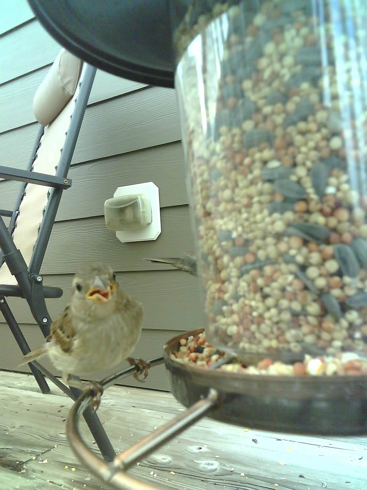
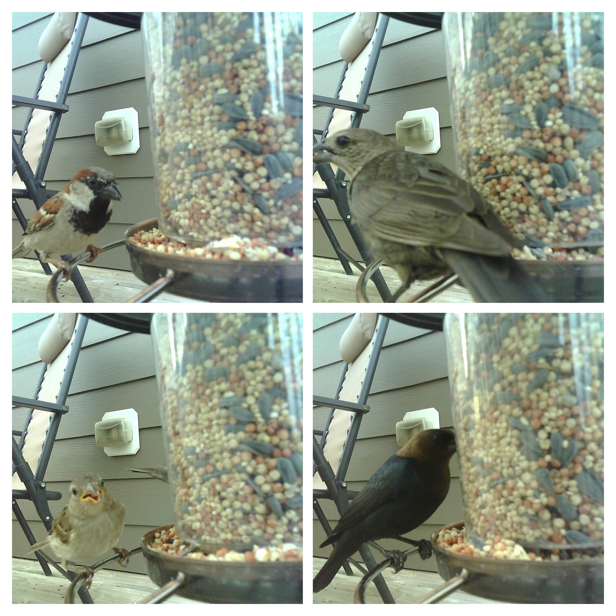
In this post, I’m going to share what I built and talk about some cool things I learned a long the way. Here are some of the cool closeup shots of the birds I was able to take:
My Project
So basically I needed an autonomous camera that would take pictures on motion. If I got too close to the feeder, the birds would fly away. So I needed something I could leave running. I also wanted it to take pictures only when it saw motion, rather than just running all the time.
I found a great post on how to build an ESP32 Camera with Motion Capture setup at randomnerdtutorials.com which basically covered all that I needed. They do a lot of great posts for people new to IoT projects and I highly recommend them as a resource if you are looking to build this (or other) IoT projects. They have source code and a bill of materials, as well as tips and step by step instructions on how to hook everything up.
The basic setup does the following:
- the motion sensor watches for any activity
- the motion sensor picks up motion
- the camera module is awakened from being “asleep” and takes a picture
- the picture is captured with an onboard SD card
- the camera module goes back to sleep
The cool part is that you can leave this running autonomously, and when you want to get the pictures you just grab the SD card and put it in your computer. Also, since it keeps the ESP32 in low power (sleep) when not in use, it makes it great with a battery.
Materials
So to build the project that I made, you can find most of the materials off of Amazon for relatively cheap. Here are some links to what I used:
- ESP32 Camera Module and Development Board
- Waterproof Enclosure
- FTDI Programmer
- Motion Sensor
- Jumper Wires
- Transistors
- SD Card
- Breadboard
I also used cable ties, heat shrink, and old USB cable that I stripped for the battery connector and a glue gun for the final assembly. These are all optional and are based on what you want to do. I also used a 5V USB battery for my project, but you should be able to plug that into an adapter and have options there.
Building My Project From Tutorial to Finished Product
I started by copying the code from the tutorial and then hooking up my ESP32 Camera Module to the FTID programmer so I could load it onto the device. I used the Arduino IDE to do this, and at this stage the project looked like this:
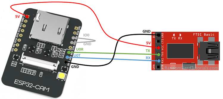
I copied this picture from the randomnerdtutorials.com post
The actual program that I used was just a straight copy from the tutorial. Note that you could modify this to change things like when to flash the camera etc. I left it as is since it was simple enough and did all of what I wanted. Here is a copy of the program:
// this program was originally copied from
// https://randomnerdtutorials.com/esp32-cam-pir-motion-detector-photo-capture/

#include "esp_camera.h"
#include "Arduino.h"
#include "FS.h"                // SD Card ESP32
#include "SD_MMC.h"            // SD Card ESP32
#include "soc/soc.h"           // Disable brownour problems
#include "soc/rtc_cntl_reg.h"  // Disable brownour problems
#include "driver/rtc_io.h"
#include <EEPROM.h>            // read and write from flash memory
// define the number of bytes you want to access
#define EEPROM_SIZE 1

RTC_DATA_ATTR int bootCount = 0;

// Pin definition for CAMERA_MODEL_AI_THINKER
#define PWDN_GPIO_NUM     32
#define RESET_GPIO_NUM    -1
#define XCLK_GPIO_NUM      0
#define SIOD_GPIO_NUM     26
#define SIOC_GPIO_NUM     27
#define Y9_GPIO_NUM       35
#define Y8_GPIO_NUM       34
#define Y7_GPIO_NUM       39
#define Y6_GPIO_NUM       36
#define Y5_GPIO_NUM       21
#define Y4_GPIO_NUM       19
#define Y3_GPIO_NUM       18
#define Y2_GPIO_NUM        5
#define VSYNC_GPIO_NUM    25
#define HREF_GPIO_NUM     23
#define PCLK_GPIO_NUM     22

int pictureNumber = 0;

void setup() {
  WRITE_PERI_REG(RTC_CNTL_BROWN_OUT_REG, 0); //disable brownout detector
  Serial.begin(115200);

  Serial.setDebugOutput(true);

  camera_config_t config;
  config.ledc_channel = LEDC_CHANNEL_0;
  config.ledc_timer = LEDC_TIMER_0;
  config.pin_d0 = Y2_GPIO_NUM;
  config.pin_d1 = Y3_GPIO_NUM;
  config.pin_d2 = Y4_GPIO_NUM;
  config.pin_d3 = Y5_GPIO_NUM;
  config.pin_d4 = Y6_GPIO_NUM;
  config.pin_d5 = Y7_GPIO_NUM;
  config.pin_d6 = Y8_GPIO_NUM;
  config.pin_d7 = Y9_GPIO_NUM;
  config.pin_xclk = XCLK_GPIO_NUM;
  config.pin_pclk = PCLK_GPIO_NUM;
  config.pin_vsync = VSYNC_GPIO_NUM;
  config.pin_href = HREF_GPIO_NUM;
  config.pin_sscb_sda = SIOD_GPIO_NUM;
  config.pin_sscb_scl = SIOC_GPIO_NUM;
  config.pin_pwdn = PWDN_GPIO_NUM;
  config.pin_reset = RESET_GPIO_NUM;
  config.xclk_freq_hz = 20000000;
  config.pixel_format = PIXFORMAT_JPEG;

  pinMode(4, INPUT);
  digitalWrite(4, LOW);
  rtc_gpio_hold_dis(GPIO_NUM_4);

  if(psramFound()){
    config.frame_size = FRAMESIZE_UXGA; // FRAMESIZE_ + QVGA|CIF|VGA|SVGA|XGA|SXGA|UXGA
    config.jpeg_quality = 10;
    config.fb_count = 2;
  } else {
    config.frame_size = FRAMESIZE_SVGA;
    config.jpeg_quality = 12;
    config.fb_count = 1;
  }

  // Init Camera
  esp_err_t err = esp_camera_init(&config);
  if (err != ESP_OK) {
    Serial.printf("Camera init failed with error 0x%x", err);
    return;
  }

  Serial.println("Starting SD Card");

  delay(500);
  if(!SD_MMC.begin()){
    Serial.println("SD Card Mount Failed");
    //return;
  }

  uint8_t cardType = SD_MMC.cardType();
  if(cardType == CARD_NONE){
    Serial.println("No SD Card attached");
    return;
  }

  camera_fb_t * fb = NULL;

  // Take Picture with Camera
  fb = esp_camera_fb_get();
  if(!fb) {
    Serial.println("Camera capture failed");
    return;
  }
  // initialize EEPROM with predefined size
  EEPROM.begin(EEPROM_SIZE);
  pictureNumber = EEPROM.read(0) + 1;

  // Path where new picture will be saved in SD Card
  String path = "/picture" + String(pictureNumber) +".jpg";

  fs::FS &fs = SD_MMC;
  Serial.printf("Picture file name: %s\n", path.c_str());

  File file = fs.open(path.c_str(), FILE_WRITE);
  if(!file){
    Serial.println("Failed to open file in writing mode");
  }
  else {
    file.write(fb->buf, fb->len); // payload (image), payload length
    Serial.printf("Saved file to path: %s\n", path.c_str());
    EEPROM.write(0, pictureNumber);
    EEPROM.commit();
  }
  file.close();
  esp_camera_fb_return(fb);

  delay(1000);

  // Turns off the ESP32-CAM white on-board LED (flash) connected to GPIO 4
  pinMode(4, OUTPUT);
  digitalWrite(4, LOW);
  rtc_gpio_hold_en(GPIO_NUM_4);

  esp_sleep_enable_ext0_wakeup(GPIO_NUM_13, 0);

  Serial.println("Going to sleep now");
  delay(1000);
  esp_deep_sleep_start();
  Serial.println("This will never be printed");
}

void loop() {

}
The high level walkthrough of this program is that the ESP32 Camera Module stays in a “sleep” mode, and only wakes when motion happens. If you’re familiar with the Arduino IDE format of programs, you have a setup and a loop function. You’ll note that the setup function has all of the program code as there isn’t a “running” state but rather just the camera wakes up, takes a picture, and goes back to sleep.
In order to install the code on the ESP32 Camera Module, you’ll need to connect a cable to a FTDI programmer. The pins and setup of the ESP32 Camera Module are not designed the same way other Arduino Devices are, so you have to do this as an intermediary to properly load the code from your computer to the device.
Building the basic circuit
Once I had that setup, I built a basic circuit with a breadboard (follow the tutorial of course) and I got here:
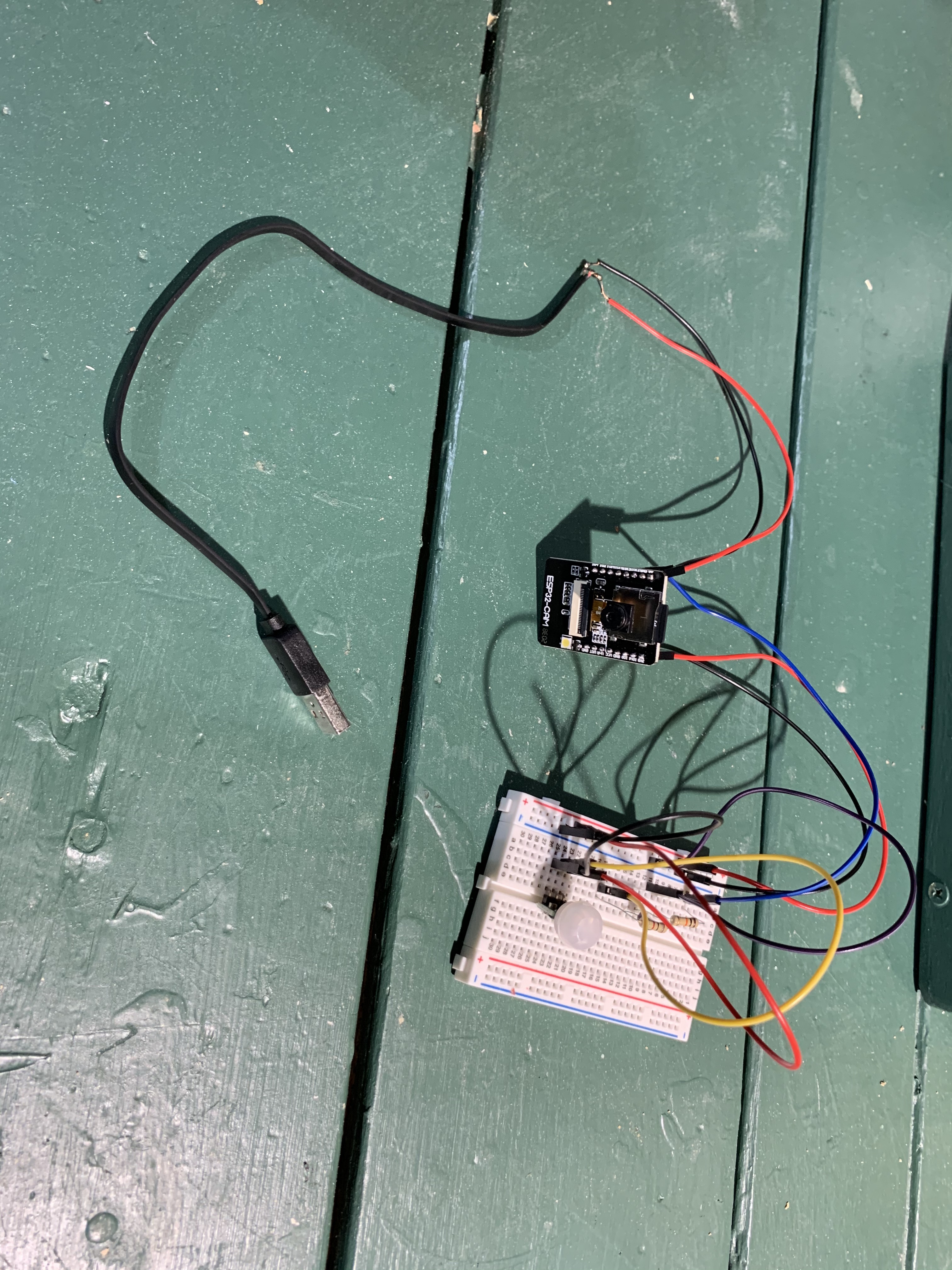
I tested it out and got pictures, from there I then soldered the wires together where necessary so I didn’t need the breadboard. The end product here was the following:
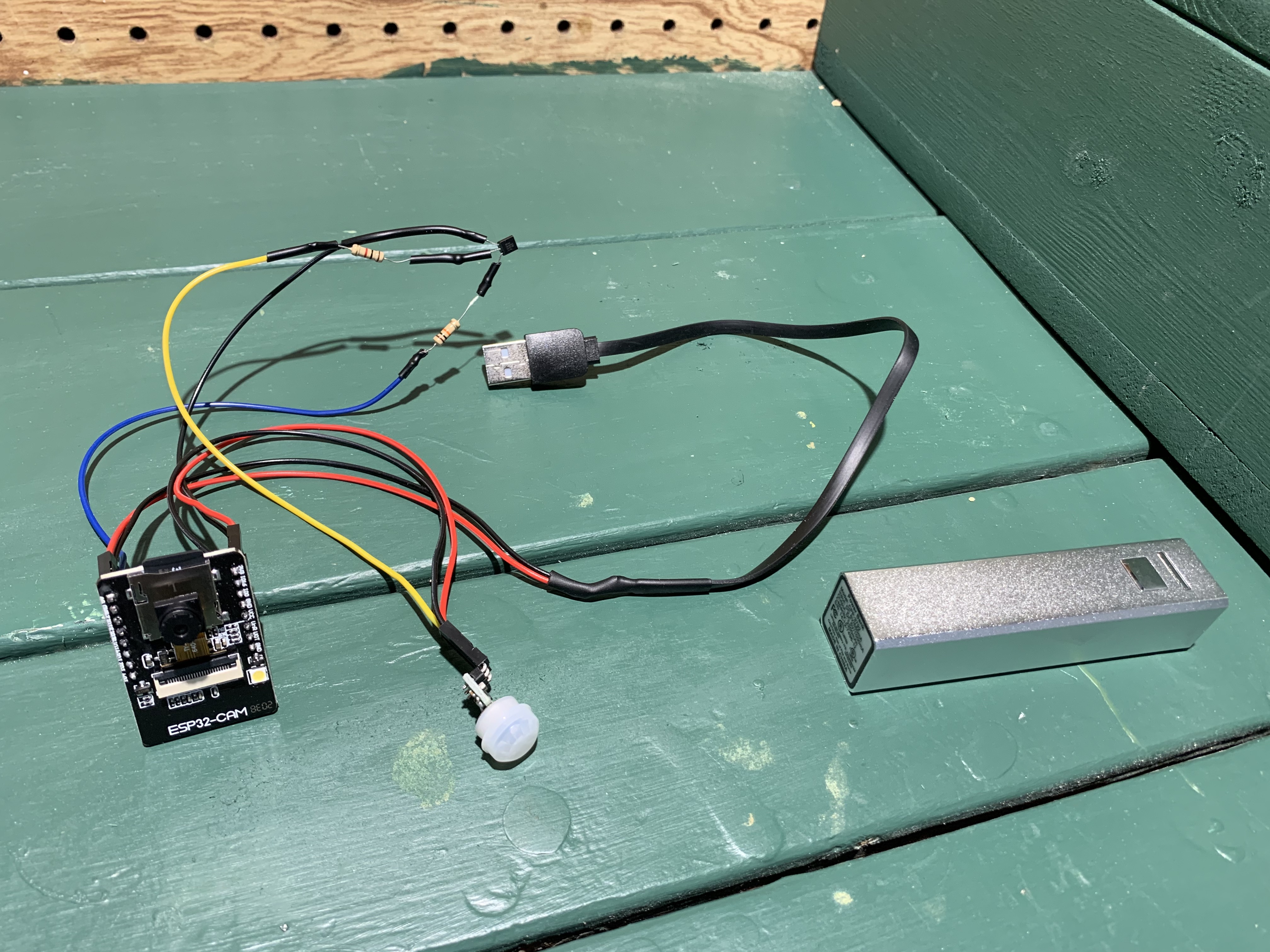
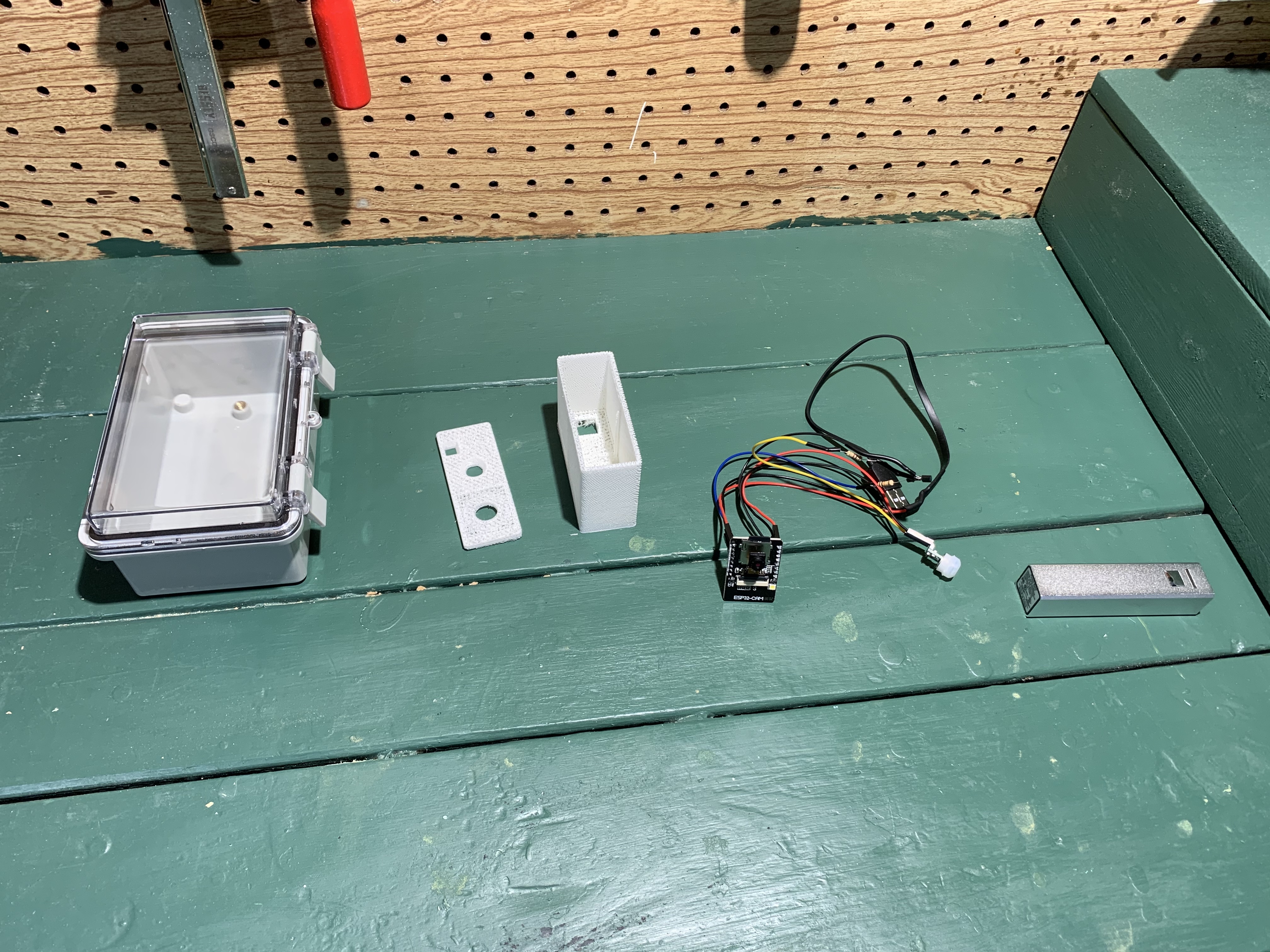
I tested my soldered circuit and again got pictures so I was good to go. Now I needed a housing so I could protect it outside. I also 3D Printed a small box that I could fit the wires etc. into so it made it neatly organized when it was finished. Here are all the parts before assembly:
So then I went ahead and connected everything together. I used a hot glue gun to glue the parts in place inside the enclosure. Unfortunately, I found that both the camera and the motion sensor didn’t operate very well inside the enclosure. The additional layer of plastic that is the front of the enclosure blocked both of them enough where they didn’t function properly. So to fix this I ended up having to drill holes for both the camera and the motion sensor. The end product looked like this:
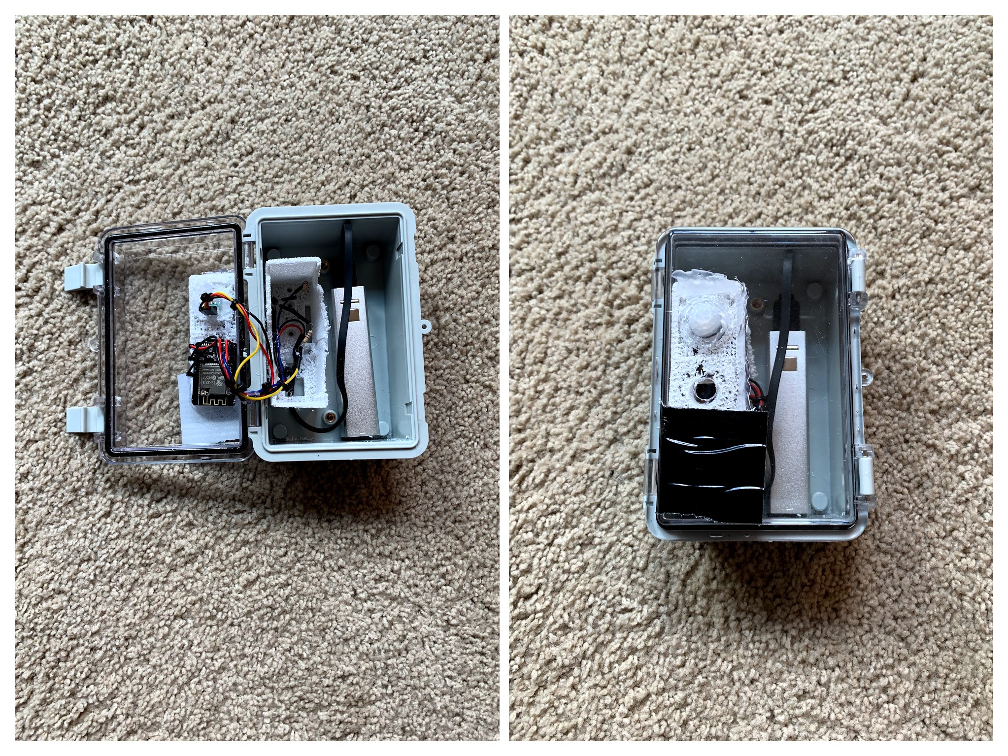
If you noticed the Duct Tape on the front, its blocking the flash. The original project that I copied the code from used the flash on every picture. I was concerned this might scare the birds so put the Duct Tape there to block it. You can actually change it in code, but since I had already assembled everything I decided not to try and hook up the FTDI programmer and go through all that hassle. Plus it looks cooler (I think).
My project in action
So once I got it working, I went ahead and zip tied the camera to our bird feeder:
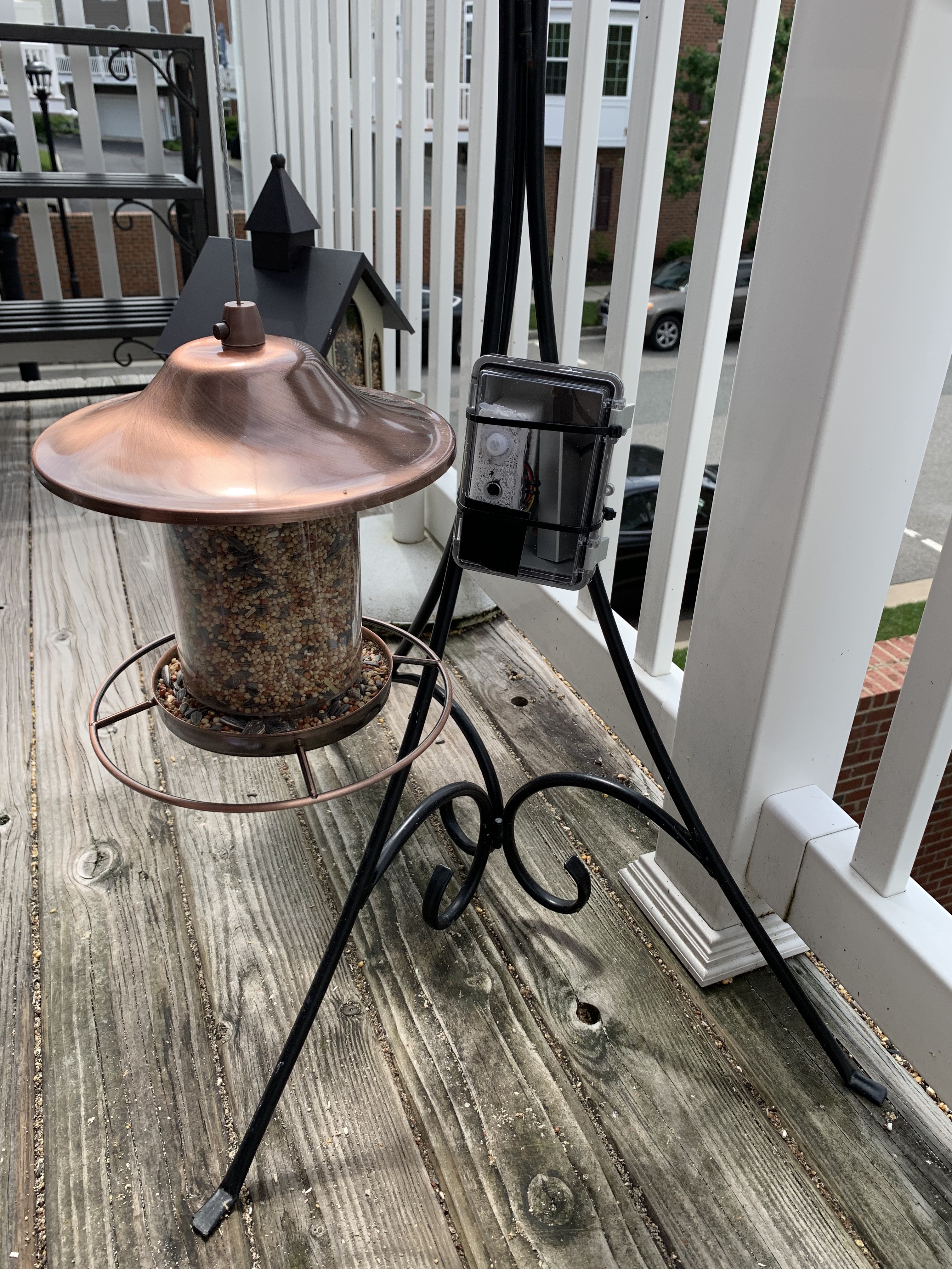
I left it in place and then went back a few hours later to see the pictures in action. Here are a few of my favorites:
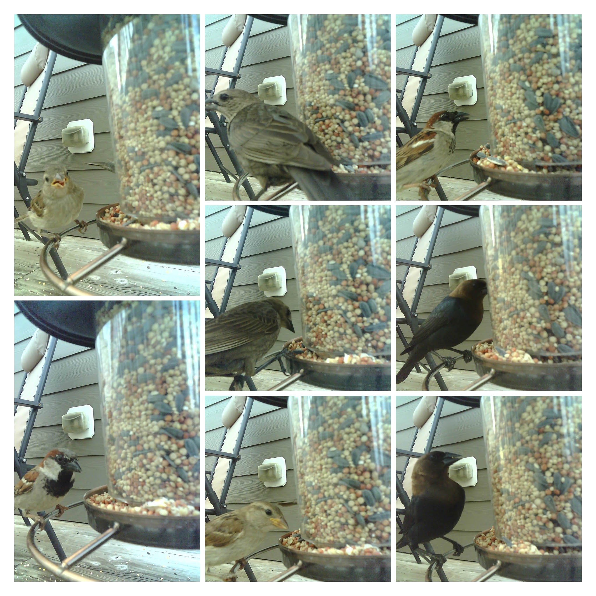
I even got an action shot of one of the birds basically going crazy with the seed. If you look closely you can see the bird seed flying in midair:
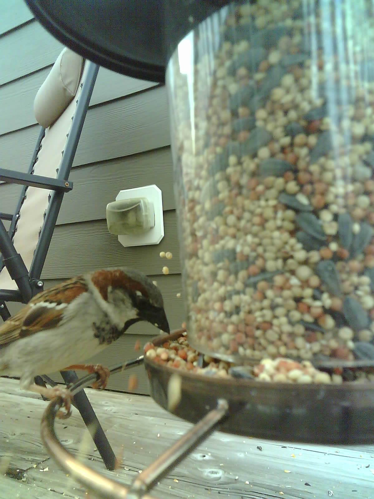
I really liked how you can get closeup pictures of the birds. So far we’ve got pictures of several of them, but there is a cardinal we are hoping to get a picture of as well as some Mourning Doves that come back frequently.
I’ve tried a few times with the camera attached to the feeder. I’m going to attempt a few more times with it in different locations.
Closing Thoughts
I hope you’ve enjoyed reading about my little project. This is definitely a fun project if you have some wildlife you’d like to follow. It’s also just a fun use of motion sensors and the camera module. Most of the parts are fairly inexpensive and it wasn’t that difficult to setup. If you wanted to do this, I’d recommend iteratively working through the project like I did. I learned things in each step, and it was a fun finished project to share with your family.